Solutions
10 kV insulated bracket
HIGH-VOLTAGE CABLE SUPPORT with Copoprotec® coating
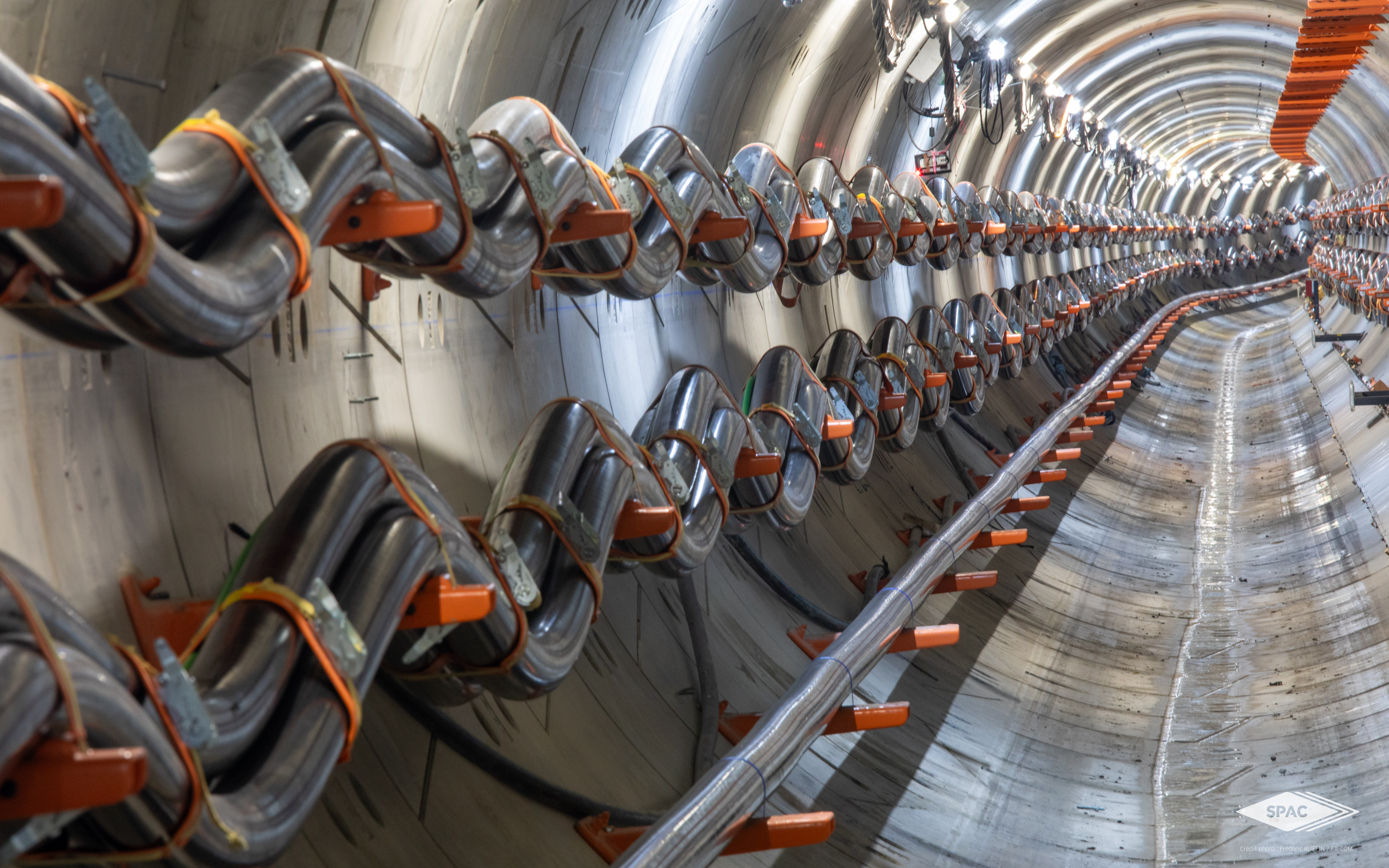
The Copoprotec® insulated brackets and consoles can support all types of HTB3-HTB2-HTB1/HTA/LV cables, in cable tunnels, third-party structures such as road or railway bridges, tunnels, or in electrical substations.


Patent pending
France No. FR1902985
Identified file
RTE/CNER AE-BCS-16- 00004 ind 5 from 28/04/20
RST / RTE
Compliant with RST / RTE Part 6 - 2019


10 kV INSULATED BRACKETS WITH COPOPROTEC® COATING
DIELECTRIC RESISTANCE
10 kV preventing the flow of short-circuit current through the bracket.
BREAKDOWN RESISTANT
HTB cable with a 31.5 kA Icc and a 150 ms Tcc
SELF-EXTINGUISHING COATING
Copoprotec® self-extinguishing coating
Calorific value < 5 MJ/kg
RESISTANT
Resistant to mechanical and chemical aggression
Description
The Copoprotec® coating used on steel brackets provides a guaranteed dielectric resistance of 10kV, as well as excellent resistance to impacts and chemical aggression.
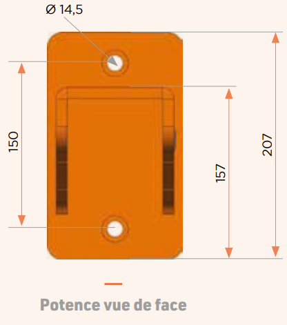
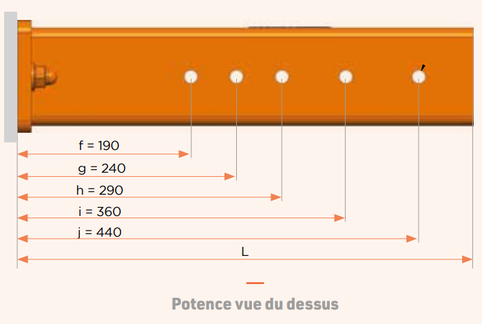
The range of Copoprotec® brackets is available in several lengths and offers two types of vertical load resistance (LIGHT 700daN, HEAVY 1200daN).
The Copoprotec® insulated brackets are compatible with all types of equipment certified by RTE/CNER.
The design of the Copoprotec® bracket can be customized upon request to accommodate lower or higher loads, specific lengths, or particular supports (such as a tubular voussoir).
There are multiple fixing and mounting methods for insulated brackets (on the wall, on self-supporting poles or structures, etc.) and they are adapted to the configuration of the installation, whether it is already existing or new.

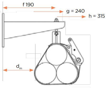
HOW TO CHOOSE YOUR 10 KV COPOPROTEC INSULATED BRACKET?
The choice of a 10kV insulated bracket is determined by:
- The loads to be supported depending on the type of cable (diameter, aluminum/copper, manufacturer, distance between brackets, etc.).
- The implementation efforts (such as cable laying, snaking, etc.)
- The combing drawing in order to comply with the minimum radius of curvatures of the cables (20 x cable ∅)
- The distance to be maintained to ensure that the thermal proximity effect is negligible (IEC 60287-2-2 standard) must be at least ≥ 0.5 x cable diameter.
EXAMPLE
If the cable bundle is suspended in a 190 mm cloverleaf configuration,
- dm ≥ 0.5 cable ∅
- max cable ∅ = 190 / 1.5 = 126
NOTE: this example is solely provided for information purposes.


Reference table

Videos
Realisations


